


Accelerometer: A Complete Guide to Principle and Selection
An accelerometer is an electromechanical sensor that measures the acceleration of an object. Its core physical quantity is proper acceleration—the acceleration an object actually experiences relative to free fall, expressed in units of m/s² or g (where 1 g ≈ 9.81 m/s²). Unlike coordinate acceleration, proper acceleration is independent of the reference frame, which is precisely why an accelerometer can simultaneously detect both static gravity and dynamic motion.
Inside an accelerometer, a proof mass is typically suspended within the sensor frame by flexible beams or springs. When external acceleration acts on the device, the proof mass undergoes inertial displacement relative to the frame. This displacement is proportional to the acceleration, and by detecting the physical property changes caused by this displacement, the acceleration value can be derived.
MEMS Accelerometer Operating Principle
Modern accelerometers predominantly employ Micro-Electro-Mechanical Systems (MEMS) technology, integrating mechanical structures and electronic circuits onto a single silicon chip. The operational workflow follows a chain conversion: acceleration → mechanical displacement → physical property change → electrical signal → digital output.
Taking a capacitive MEMS accelerometer as an example: when acceleration causes the proof mass to displace, the gap between the mass and the fixed electrode changes, resulting in a capacitance variation. The ASIC interface circuit can detect capacitance changes as small as 1 aF (10⁻¹⁸ F). After amplification, demodulation, and filtering, an electrical signal proportional to acceleration is output.
It is worth noting that an accelerometer at rest on the ground will read approximately −9.81 m/s² on its vertical axis. This occurs because gravity acts on the movable proof mass while the housing is constrained by the ground. Conversely, an accelerometer in free fall will read zero, because both the proof mass and the housing are in free fall simultaneously, resulting in zero relative displacement.
Major Accelerometer Technology Types
Type | Working Principle | Key Characteristics | Typical Applications |
Capacitive | Detects capacitance change between plates | Low power, high precision, suitable for low-frequency motion | Smartphones, wearables, attitude detection |
Piezoelectric | Piezoelectric material generates charge under force | High-frequency response, ideal for vibration and shock measurement | Industrial vibration monitoring, structural health diagnosis |
Piezoresistive | Mechanical stress induces resistance change | Covers both static and dynamic, strong shock resistance | Automotive crash testing, harsh environment measurement |
Thermal | Detects temperature distribution change from heated air bubble displacement | No moving parts, ultra-high shock resistance (up to 50,000 g) | Automotive electronics, high-reliability scenarios |
Servo (Force-Balance) | Feedback control force keeps proof mass stationary | Extremely high precision, low drift | Inertial navigation, seismic monitoring |
Resonant | Detects structural resonant frequency shift | High resolution, excellent long-term stability | Precision structural monitoring |
Popular Models and Selection Guide
The current MEMS accelerometer market is dominated by four major manufacturers—Analog Devices (ADI), STMicroelectronics (ST), Bosch, and TDK InvenSense—each with product portfolios spanning different accuracy grades and application scenarios.
1. Popular Consumer-Grade Models
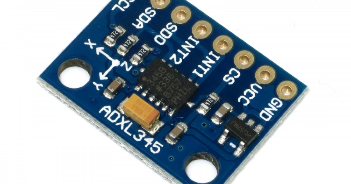
● ADI ADXL345: A classic tri-axis digital accelerometer with ±2/4/8/16 g ranges, dual I²C/SPI interfaces, 3.9 mg/LSB resolution, and power consumption as low as 0.03 mA. It is the preferred entry-level model for embedded development and prototyping.
● TDK InvenSense ICM-42688-P: A performance benchmark in the consumer-grade segment, featuring noise density as low as 75 μg/√Hz, angle drift below 1°/min at ±2 g range, and programmable bandwidth. Ideal for drone flight control and VR devices.
● Bosch BMI270: Integrates a machine learning classifier; motion wake-up mode consumes only 1.2 μA, capable of directly outputting motion types (running/walking/stationary), eliminating the need for algorithm development on the MCU side.
● ST LIS2DW12: An ultra-low-power tri-axis accelerometer supporting free-fall, wake-up, and activity/inactivity detection, suitable for wearables and asset tracking.
2. Popular Industrial-Grade Models
● ADI ADXL356/ADXL357: Tri-axis industrial accelerometers with ±40 g range, 1.5 kHz bandwidth, and operating temperature of −40 °C to 125 °C, ideal for bearing vibration analysis and structural health monitoring.
● ST IIS3DHHC: A high-bandwidth accelerometer with bandwidth up to 11 kHz, suitable for precise vibration analysis of gear mesh frequencies and bearing characteristic frequencies.
● ADI ADXL375: A ±200 g high-range digital accelerometer specifically designed for shock detection with strong shock resistance.
When selecting an accelerometer, noise density is the most easily overlooked parameter yet the one that determines actual precision. A sensor with 400 μg/√Hz noise density may have a nominal 16-bit resolution, but its actual effective bits may be only 10. Noise integrates into angle estimation, causing "angle drift while stationary." Additionally, the nonlinear nature of temperature drift means that low-end sensors cannot be adequately compensated through software calibration alone; high-end sensors with built-in temperature compensation circuits are the fundamental solution.
Development Trends
Current MEMS accelerometers are evolving toward higher precision, lower power consumption, and greater integration. Multi-sensor fusion has become the mainstream trend: six-axis IMUs integrating tri-axis accelerometers with tri-axis gyroscopes, and nine-axis combo sensors further incorporating magnetometers, provide complete motion perception capabilities for complex scenarios. Meanwhile, domestic MEMS accelerometers continue to achieve breakthroughs in structural design, vacuum packaging, and full-temperature-range compensation, progressively replacing overseas products in the industrial-grade and tactical-grade markets.
Website: www.conevoelec.com
Email: info@conevoelec.com


