


Power Regulator: LDO vs. Buck Converter – Principles, Comparison, and Selection
In electronic system design, power management serves as the cornerstone of overall performance and reliability. One of the most fundamental requirements across virtually all circuits is the conversion of a higher DC input voltage to a lower, stable output voltage. The two mainstream solutions that accomplish this task—the low-dropout linear regulator (LDO) and the buck converter (step‑down switching regulator)—share the same objective, yet their operating mechanisms, performance characteristics, and application domains are fundamentally distinct.
Working Principles: Linear Regulation vs. Switching Chopping
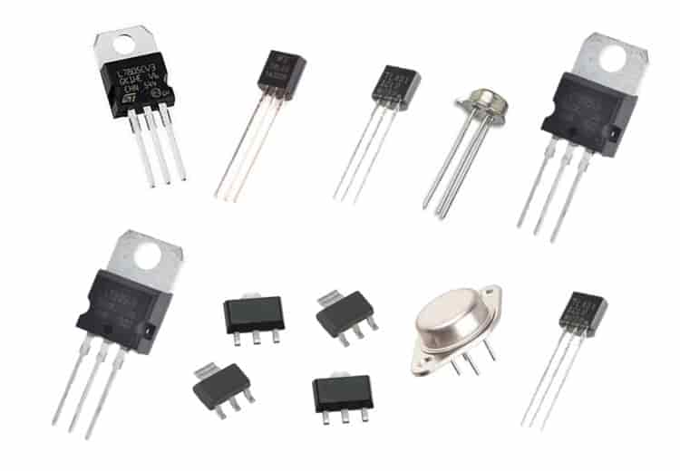 An LDO is, at its core, a linear voltage regulator. Its essential concept is to treat the series pass transistor (the power device connected between input and output) as a variable resistor. An error amplifier continuously monitors the output voltage and adjusts the conduction of this transistor based on the feedback. Any excess voltage—the difference between the input and the desired output—is dissipated directly as heat across the pass transistor. A key advantage of LDOs is their low dropout voltage, meaning the input needs only to be marginally higher than the output to maintain regulation; dropout values can be as low as 100–200 mV.
In contrast, a buck converter belongs to the switching power supply family and employs a completely different energy‑transfer approach. Its basic topology comprises a power MOSFET switch, an inductor, a freewheeling diode (or a synchronous rectification MOSFET), and an output filter capacitor. The switch turns on and off at a high frequency (from hundreds of kHz to several MHz). During the on‑time, the input charges the inductor; during the off‑time, the inductor releases its stored energy to sustain the load. By precisely controlling the ratio of the on‑time to the total switching period (the duty cycle), the output voltage can be regulated. In this process, energy is temporarily stored in the inductor's magnetic field rather than being consumed as heat.
Key Performance Metrics: LDO vs. Buck Converter
The fundamental differences in operating principles directly manifest in the following critical parameters:
1. Efficiency and Thermal Dissipation. This is the most pronounced differentiator. The efficiency of an LDO is approximately equal to the ratio VOUT/VIN. When the input‑output voltage differential is large, efficiency drops sharply, and most of the power is converted into heat, leading to severe thermal management challenges. The buck converter, however, avoids continuous high power loss across a pass element by switching; its efficiency typically reaches 80%–95%, and it remains highly efficient even under large voltage differentials.
2. Output Noise and Ripple. Because an LDO operates linearly without any switching action, its output is exceptionally clean, with ripple below 1 mV and noise under 100 µV rms. The buck converter's switching action inevitably introduces output ripple (typically in the range of 10–30 mV p‑p) and electromagnetic interference (EMI), necessitating additional filtering measures.
3. Circuit Complexity and Cost. An LDO requires very few external components—typically just one or two capacitors on each side. The buck converter, on the other hand, demands an inductor, multiple capacitors, a control IC, and careful PCB layout design, significantly increasing component count and board area.
4. Quiescent Current. LDOs can achieve quiescent currents as low as a few microamperes, or even 1 µA. Buck converters typically draw hundreds of microamperes up to several milliamperes.
Characteristic | LDO | Buck Converter |
Efficiency | VOUT/VIN; drops significantly with high VIN‑VOUT | 80%–95%; remains high even with large differential |
Output ripple / noise | Very low (<1 mV, <100 µV rms) | Higher (10–30 mV p‑p), requires filtering |
Thermal dissipation | High (voltage differential × current) | Low |
External components | Minimal (1–2 capacitors) | More (inductor, capacitors, MOSFETs, etc.) |
Quiescent current | Extremely low (down to 1 µA) | Higher (hundreds µA to mA) |
EMI | None | Present, needs suppression |
Typical load current capability | Usually ≤2 A | Up to tens of amperes |
Selection Strategy
In essence, the core logic of selection can be summarised as: choose a buck converter for high voltage differential and high load current; choose an LDO for low differential, low power, and low noise.
When the input‑output voltage difference is large (e.g., 12 V to 3.3 V) or the load current exceeds several hundred milliamperes, the thermal dissipation of an LDO becomes unacceptable, making a buck converter the inevitable choice. In battery‑powered portable devices, where the differential is small (e.g., 3.7 V to 3.3 V) and the load current is modest, an LDO provides efficient regulation with the simplest circuitry and the lowest quiescent current. For applications that demand exceptionally clean power—such as ADCs, RF circuits, and audio front‑ends—the LDO’s superior noise and ripple performance makes it irreplaceable.
In practice, these two solutions are often combined in a cascaded architecture: a buck converter first steps down a high bus voltage (e.g., 12 V) efficiently to an intermediate level (e.g., 3.6 V), and then an LDO performs the final precision regulation and noise filtering. This two‑stage approach delivers both high overall efficiency and superior output quality, and is a common practice in high‑performance system design.
Understanding the intrinsic differences and application boundaries between LDOs and buck converters is the foundation for making sound power‑supply selection decisions. There is no absolute superiority of one over the other; the right choice depends entirely on how the specific application prioritises efficiency, noise, cost, size, and thermal management.
Website: www.conevoelec.com
Email: info@conevoelec.com


