


Infineon Power ICs: Popular Classic Series and Selection Guide
As a global leader in power semiconductors, Infineon Technologies structures its power device portfolio around IGBTs as the foundation, complemented by SiC and GaN as the two growth pillars. The product range covers everything from low ‑voltage consumer electronics to ultra‑high‑voltage railway and industrial applications. This article systematically reviews Infineon's most popular classic power device series and their selection logic, helping engineers quickly identify the optimal solution for their designs.
I. Low‑Voltage MOSFETs – OptiMOS™ Family
The OptiMOS™ family is Infineon's flagship low‑voltage power MOSFET line, covering voltages from 15 V to 300 V, and is renowned for its ultra‑low on‑resistance (RDS(on)) and high switching frequency.
● OptiMOS™ 7 – The 40 V series is specifically designed for automotive motor drives and power distribution, offering excellent avalanche ruggedness. Representative models include IAUCN04S7N005ATMA1, IAUCN04S7L004ATMA1, and IPC100N04S4‑02. The 25 V series targets 48 V intermediate bus converters for AI core power supplies.
● OptiMOS™ 6 – Available in 100 V, 120 V, and 200 V versions, suitable for switch‑mode power supplies (SMPS), solar inverters, power tools, and battery management systems. In the 200 V class, typical part numbers are IPB068N20NM6ATMA1, IPB095N20NM6ATMA1, and ISC130N20NM6ATMA1.
● OptiMOS™ 5 – Offered in 25 V and 30 V variants, delivering the highest power density and efficiency. An example is IPP075N15N3 G, which achieves a 40% reduction in RDS(on) compared to its predecessor.
It is worth noting that for low-voltage scenarios, OptiMOS™ is the first choice - for high-switching-frequency applications, OptiMOS™ 6/7 should be selected, and considering cost and performance, OptiMOS™ 5 can be considered. Automotive‑grade designs must use AEC‑Q101 qualified variants.
II. High‑Voltage MOSFETs – CoolMOS™ Family
The CoolMOS™ family represents Infineon's high‑voltage super‑junction MOSFET technology, covering voltages from 500 V to 950 V, and strikes an excellent balance between efficiency and ease of use. It includes six sub‑families: C7, G7, CFD7, P7, S7, and PFD7. The most popular series and models are:
● CoolMOS™ 7 – 7th‑generation super‑junction MOSFETs covering 600 V to 950 V, with further optimized switching and conduction losses compared to the previous C6/P6 generations.
● CoolMOS™ P7 – 600 V series, an upgrade of P6, balancing high efficiency with design simplicity.
● CoolMOS™ CE – Optimized for consumer electronics, available in five voltage classes: 500 V, 600 V, 650 V, 700 V, and 800 V. Widely used in mobile phone chargers, notebook adapters, and LED drivers.
Additionally, integrated CoolMOS™ power IC series (e.g., ICE5AR0680AG‑1, ICE5GR2280AG‑1, ICE5BR3995AG‑1) are suited for flyback converter designs.
When selecting, it is necessary to note that for high-voltage AC-DC power supplies, CoolMOS™ should be the first choice - for charger adapters, 700V CoolMOS™ CE is recommended to handle voltage spikes. The resonant topology recommends the CoolMOS™ CFD7 series (with fast recovery diodes).
III. IGBTs – TRENCHSTOP™ Family
The TRENCHSTOP™ family is the core IGBT brand from Infineon, covering voltages from 600 V to 6500 V, and offers a good compromise between low on‑state voltage drop and low switching losses.
● TRENCHSTOP™ IGBT7 – 7th‑generation 1200 V IGBTs; the H7 series provides current ratings from 40 A to 140 A (TO‑247 package) and a junction temperature of 175 °C, making it the top choice for industrial drives. An example is the 750 V hard‑switching type IKZA50N75EH7.
● TRENCHSTOP™ 5 – Utilises ultra‑thin‑wafer technology; 650 V devices can deliver 40 A in a D²PAK package. Popular models include IGW40N65F5FKSA1, IKA08N65F5XKSA1, and IKW40N65F5FKSA1.
● IGBT Modules (IGBT4 / IGBT7) – The classic FF450R12KT4 (1200 V / 450 A, EconoDUAL™3 package) is widely used in industrial drives. New IGBT7 module introductions include FS3L40R12W2H7P_B11 (EasyPACK™2B) and F3L500R12W3H7_H11 (EasyPACK™3B, single‑phase NPC2 topology).
IV. Wide‑Bandgap Devices – CoolSiC™ and CoolGaN™
CoolSiC™ silicon carbide MOSFETs cover voltages from 650 V to 2000 V, with on‑resistances ranging from 7 mΩ to 1000 mΩ. The 650 V G2 series now includes a 75 mΩ option, targeting server power supplies, energy storage, and photovoltaic inverters. When selecting SiC, special attention must be paid to gate drive design – negative gate voltage turn‑off is mandatory to prevent parasitic turn‑on.
Notable 650 V G2 devices include IMBG65R010M2HXTMA1, IMW65R007M2H, and IMZA65R007M2H. For the 1200 V G2 series, representative parts are IMBG120R008M2HXTMA1, IMBG120R116M2HXTMA1, and IMBG120R234M2HXTMA1.
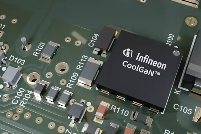
CoolGaN™ gallium nitride HEMTs focus on high‑frequency applications at 650 V and below, offering significant advantages in fast chargers and data‑centre power supplies.
● G3 series (40 V – 120 V): IGC019S06S1, IGC025S08S1, IGC037S12S1.
● G1 automotive‑qualified series (100 V): IGC033S10S1Q (3×5 mm PQFN) and IGB110S10S1Q (3×3 mm PQFN), both AEC‑Q101 certified.
V. Key Selection Guidelines for Infineon Power Chips
1. Choose the technology path first: For low‑frequency, high‑power applications (<20 kHz) with cost sensitivity, select silicon IGBTs. For high‑frequency, high‑efficiency designs (>20 kHz), choose CoolSiC™. For ultra‑high‑frequency (MHz range) and low‑to‑medium power, CoolGaN™ is the best fit.
2. Voltage derating: Select a device with a voltage rating 1.5 to 2 times the maximum operating voltage. For 400 V battery systems, use 650 V / 750 V devices; for 800 V high‑voltage platforms, choose 1200 V SiC.
3. Current derating: Allow a margin of 1.5 to 2 times the peak current, and always perform thermal derating calculations considering case temperature and the safe operating area (SOA).
Website: www.conevoelec.com
Email: info@conevoelec.com


